
Views: 0 Author: Site Editor Publish Time: 2025-09-19 Origin: Site
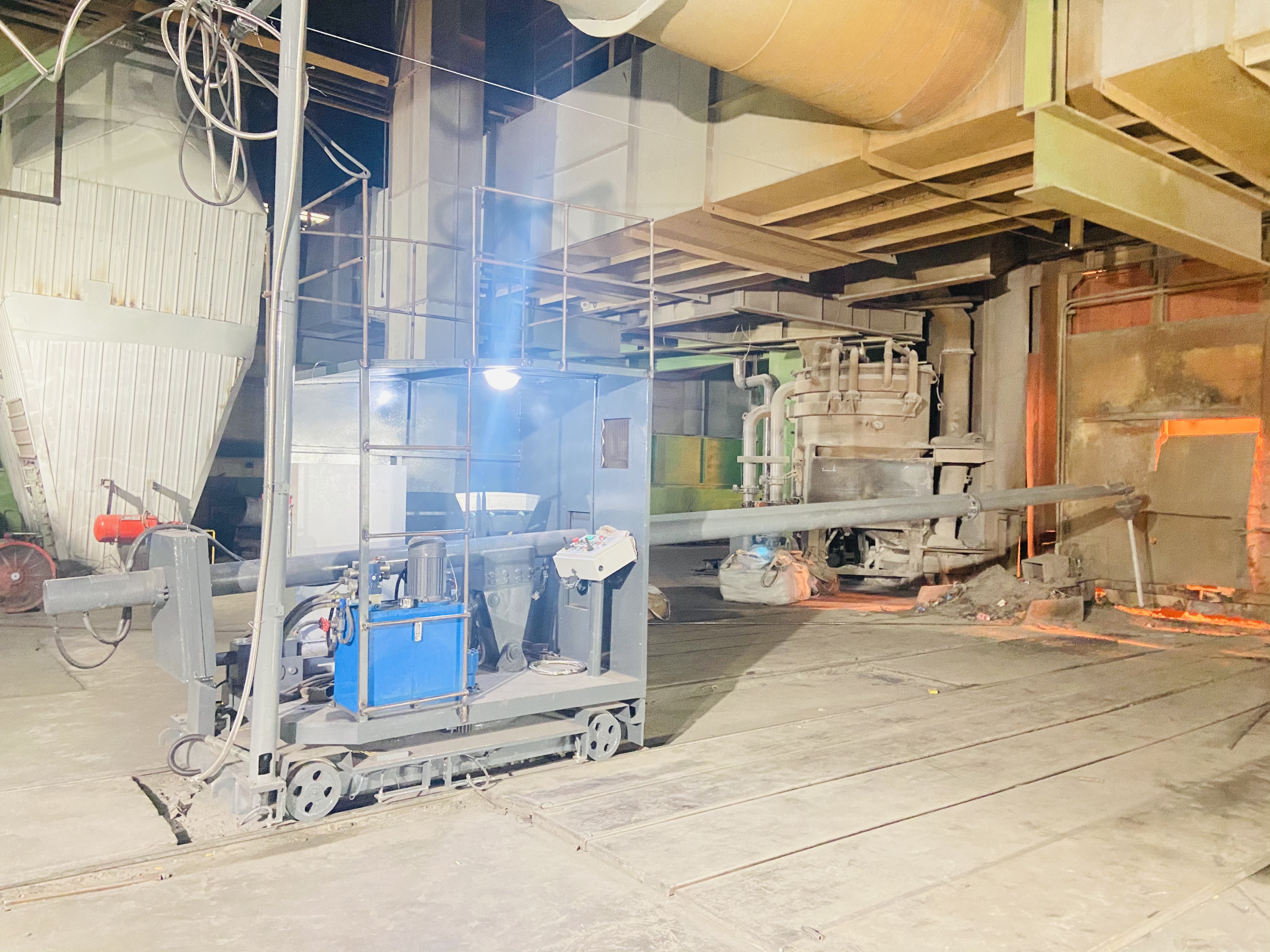
Traveling System: It is responsible for the movement of the slag stopping vehicle. Typically, it adopts a rail-type design, combined with a servo motor and a precision reducer, ensuring that the vehicle can move to the designated position with an accuracy of ±1mm before tapping. Some large-scale slag stopping vehicles are also equipped with a dual braking system to prevent the vehicle from shifting due to the impact force of molten steel during tapping.
Slag Stopping Mechanism: As the "core executive component" of the slag stopping vehicle, the mainstream designs are the "slag stopping plug pushing type" and the "slag stopping plate rotating type". The former uses a hydraulic push rod to accurately push a prefabricated slag stopping plug (made of refractory materials) into the converter tapping hole, and the density difference of the slag stopping plug is used to intercept the steel slag. The latter drives an arc-shaped slag stopping plate through a rotating shaft to block the tapping hole in the later stage of tapping, preventing the remaining steel slag from flowing in. Each of the two designs has its advantages: the slag stopping plug type is suitable for large-tonnage converters, with a slag stopping efficiency of over 95%; the slag stopping plate type is more flexible and suitable for production scenarios with small batches and multiple steel grades.
Hydraulic and Electrical Control Systems: They serve as the "brain and muscles" of the slag stopping vehicle. The hydraulic system adopts a high-pressure piston pump and a proportional valve, which can accurately control the thrust and speed of the slag stopping mechanism. For example, when pushing the slag stopping plug, the thrust can be adjusted in real-time according to the flow rate of molten steel to prevent the slag stopping plug from being washed away by the molten steel. The electrical control system is equipped with a PLC (Programmable Logic Controller) and a touch screen, supporting both manual and automatic modes. Operators can complete the slag stopping process through preset programs. At the same time, the system collects real-time data such as pressure, position, and temperature. In case of abnormalities (such as the slag stopping plug not being in place or insufficient hydraulic pressure), it immediately triggers an alarm and pauses the operation to ensure production safety.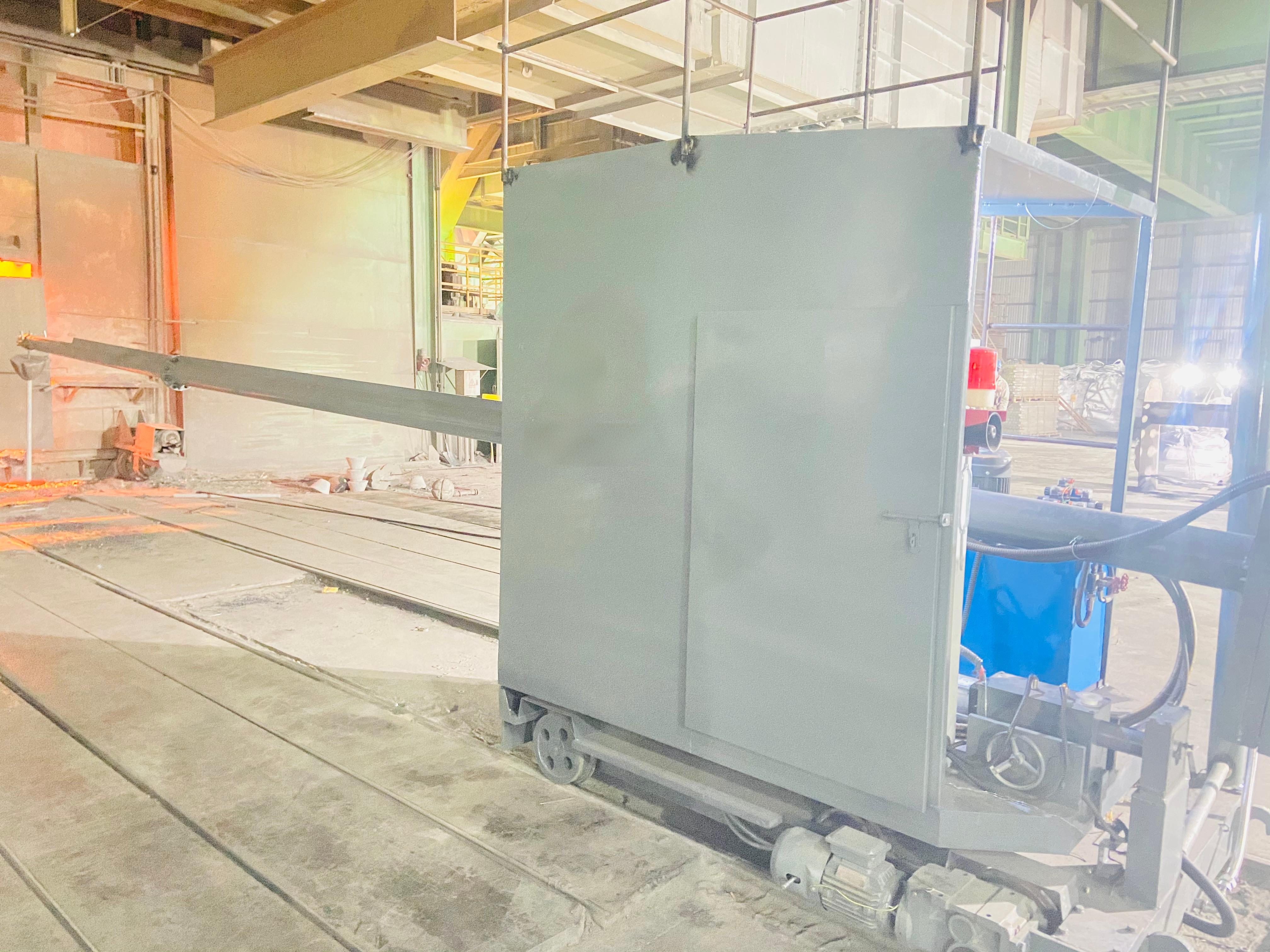
Preparation Stage: When converter steelmaking is about to end, the slag stopping vehicle moves to the preset position below the converter tapping hole through the traveling system. The slag stopping mechanism resets to the standby state, and the pressure of the hydraulic system rises to the working value (usually 16 - 20MPa) to wait for the tapping signal.
Slag Stopping Stage: The converter starts to tilt for tapping. When the outflow of molten steel reaches approximately 90% of the total amount (judged by a weight sensor or an infrared liquid level gauge), the slag stopping vehicle receives a signal, and the hydraulic system drives the slag stopping mechanism to act. If it is the slag stopping plug type, the push rod pushes the slag stopping plug into the tapping hole, and the steel slag is intercepted in the converter by the slag stopping plug; if it is the slag stopping plate type, the arc-shaped plate rotates to the position below the tapping hole to block the channel for the remaining molten steel and steel slag.
Reset Stage: After tapping is completed, the converter returns to the upright position. The slag stopping vehicle resets the slag stopping mechanism, and the traveling system drives the vehicle back to the standby position. At the same time, the system automatically records the slag stopping data of this time (such as slag stopping time, thrust, and steel slag carry-over rate), providing a basis for subsequent production optimization.


