Specialized Equipment for Removing Steel Ladle Permeable Bricks
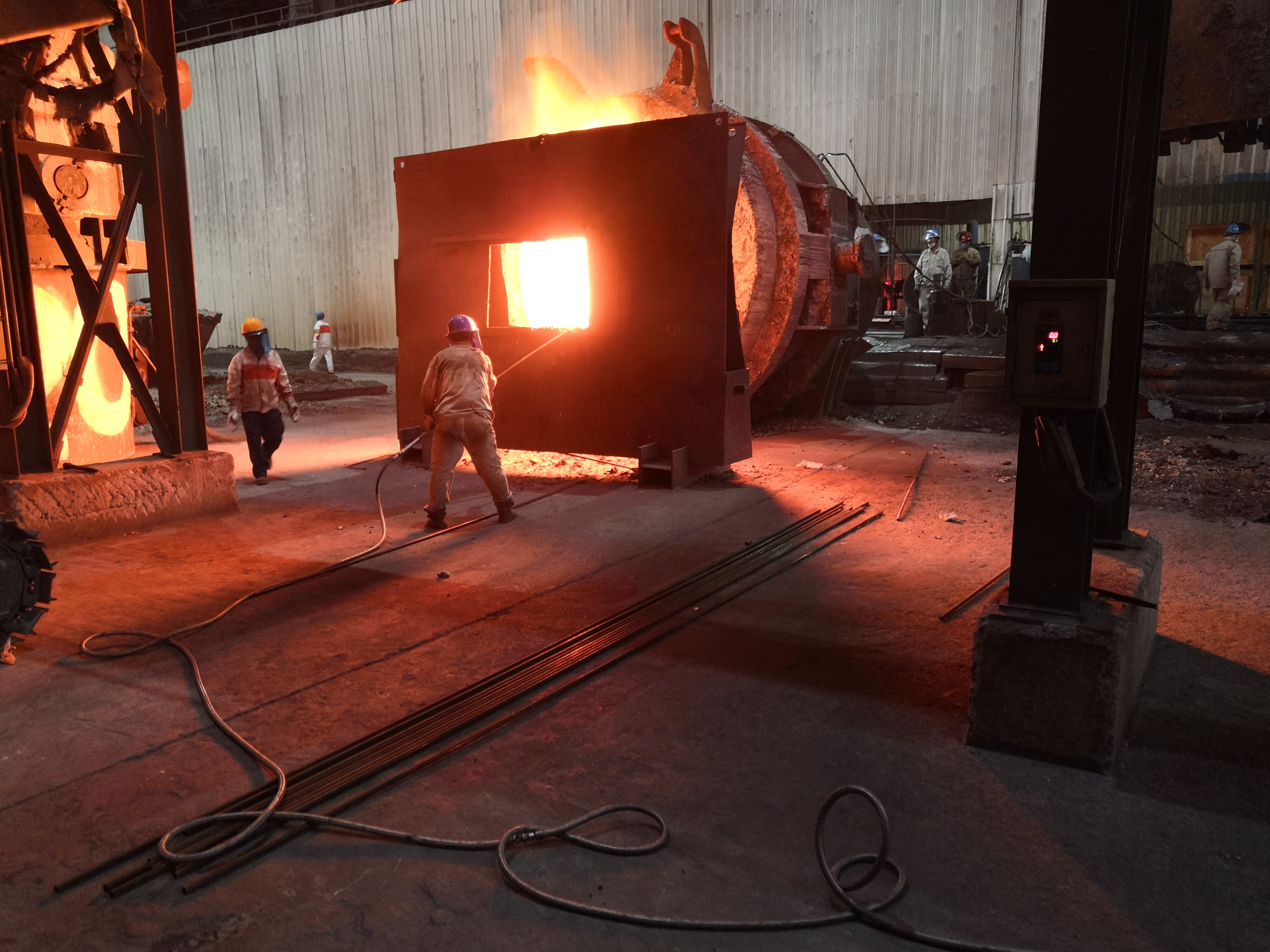
The GTJ420 Steel Ladle Permeable Brick Remover is a specialized equipment designed for the rapid replacement of argon permeable bricks in steel ladles. It is installed in the steel ladle maintenance area of steelmaking plants and is suitable for operation in high-temperature, dusty and ash-laden environments.
This equipment features advanced structure, easy operation and short auxiliary time. It adopts a 37KW independent hydraulic pump station system to control the oil cylinder, driving the sliding frame and sliding plate to move back and forth. This enables fine adjustment of the top head in both vertical and horizontal directions.
A high-power impactor is used in this machine to generate impact energy, achieving fast and accurate removal of argon permeable bricks from steel ladles.
Main Function Description - English Translation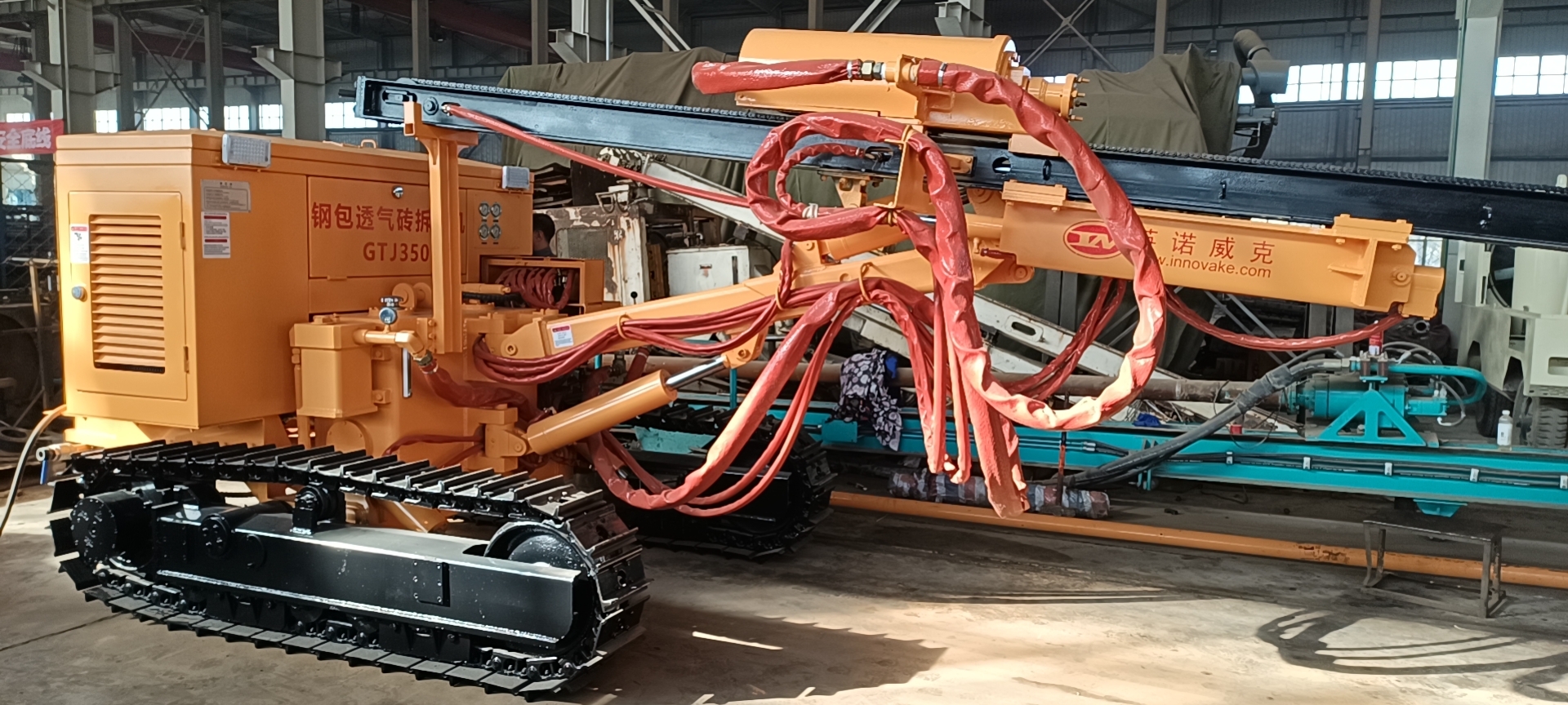
This machine consists of a sliding frame part, a propulsion mechanism, a sliding frame compensation frame, an auxiliary sliding frame, a spacer sleeve type pole holder, a sliding frame tilting and swinging device, a drill arm, a frame, and a crawler assembly.
1. Sliding Frame Part
The sliding frame adopts a welded structure. It uses hot-rolled carbon steel channels and square steel pipes as the guide rails for the sliding plate, and controls the stable lifting of the oil cylinder through a one-way throttle valve.
A roller support system is welded on the sliding frame compensation frame. It effectively supports the sliding frame's movement through four rollers and prevents excessive deformation of the sliding frame.
2. Propulsion Mechanism
The propulsion part consists of a propulsion motor, a chain, a sliding plate, and other components.
The propulsion mechanism drives the pulley block and makes the sliding plate slide back and forth on the sliding frame via the chain, thereby enabling the drill tool to move forward and backward.
A roller structure is adopted on the sliding plate, which effectively reduces the wear of the slideway.
3. Sliding Frame Compensation Frame
The sliding frame compensation frame allows the sliding frame to perform telescopic movement within a certain range, thereby achieving effective compensation for the sliding frame.
One end of it is connected to the sliding frame, and the other end is connected to the tilting device.
4. Auxiliary Sliding Frame
It is formed by butt welding of hot-rolled carbon steel channels. It is used to support the pole holder.
5. Spacer Sleeve Type Pole Holder
The machine is equipped with two spacer sleeve type pole holders, which are fixed on the auxiliary sliding frame. They are used to support the impact drill rod, prevent excessive deformation of the drill rod, and enhance the working rigidity and strength of the sliding frame.
6. Sliding Frame Tilting and Swinging Device
This device is installed in front of the drill arm. It supports the sliding frame compensation frame and the sliding frame, and completes the positioning action of the sliding frame.
7. Drill Arm
(1) Brief Introduction
The drill arm of the drilling machine is a rectangular long tube. One end is connected to the "U"-shaped component of the frame body via a hinge shaft, and the other end supports the tilting and swinging device of the drilling machine as well as the sliding frame assembly above it. A lifting oil cylinder is installed at the lower part of the drill arm, and a swinging oil cylinder is installed on the side to control the positioning of the drill arm.
(2) Drill Arm Specifications
8. Frame
The frame is a welded steel mounting base. According to the design requirements, it can withstand the stress generated during operation on various terrains. The frame is equipped with a hydraulic oil tank, a drill arm base, a console, a hydraulic pump and a diesel engine. A traction frame is installed at the rear of the frame, and a swinging oil cylinder is installed on each side of the frame. These cylinders allow the crawlers to fluctuate up and down within a range of 5 degrees, ensuring the drilling machine remains balanced and stable during walking, fixing and operation.
9. Crawler Assembly
The crawler assembly consists of left and right crawlers. Each crawler includes a traveling motor, a driving wheel, a guide wheel, a crawler hydraulic regulator, five supporting wheels, one supporting roller and a crawler plate assembly.
 Quality Assurance and After-Sales Service
Quality Assurance
Under the premise that the buyer uses and maintains the contracted equipment correctly in accordance with the Operation Manual, the quality assurance period of the equipment shall be one year from the date of delivery to the buyer or 1,000 hours of equipment operation, whichever comes first. Among them, oil seals, top heads, drill rods, and high-temperature-resistant hoses are not covered by the quality assurance.
During the quality assurance period, if quality problems occur due to manufacturing reasons, the supplier shall be responsible for solving them and bear the fault handling costs incurred therefrom.
For faults caused by quality problems during the quality assurance period that the user must handle in a timely manner to meet production needs, the user shall first inform the supplier of the fault situation and handling plan. With the supplier’s approval, the user may handle the fault first and properly keep the removed spare parts. The cost of spare parts incurred shall be borne by the supplier (except for wearing parts such as top heads, hoses, and filter elements).
For quality assurance problems that cannot be solved through telephone consultation, the supplier will arrange relevant personnel to go to the site for handling.


 Quality Assurance and After-Sales Service

